av-en-pipe 173 / 199
10秒後にBOOKのページに移動します
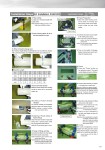
171 Installation Steps EF Installation AVEF200 Applicable Range 15 . 200mm (d20 . d225) ⑥ Cleaning of Fusion Surface of Pipe & Fittings Clean the fusion surface of pipe and fitting with a special paper towel fully impregnated with acetone. Note) Do not use tissue paper or cloth. ① Pipe Cutting Cut pipe at a necessary length with a pipe cutter. Note) Diagonal cutting of 5 mm or over may cause installation failure. ③ Entry of Insertion Gauge Line Mark insertion length (fitting overall length/2) in the circumference direction with a permanent marker, etc. Reference) Useful to use cardboard, etc. ⑦ Fixing of Fitting and Pipe Insert pipe into fitting to the insert gauge line and fix securely using clamp. Note) Insufficient pipe insertion may cause fusion failure. Note) Misalignment of pipe and fitting (oblique insertion) may cause fusion failure. Check for no angle misalignment and fix clamp. ④ Entry of Fusion Surface Mark the surface where fusion to fitting would be made with a permanent marker, etc. ⑤ Cutting of Fusion Surface (Scrape) Cut until the marked part completely disappears with a PP special scraper. Note) No cutting or uneven cutting may cause fusion failure. ⑧ Fusion Preparation 1) Open the cable housing cover on the back of unit body and take out the power source cable, output cable and bar code reader. 2) Connect the power source cable to AC 100V power source. Notes: In the case of using an extension cable, use the one provided (10x3.5mm2). Notes: Do not connect other equipment to the extension cable. 3) Turn on the switch of leakage beaker (main power source) and close the housing cover. ② Pipe Cleaning Wipe off dirt or the like attached on pipe. Size d20 (15) d25 (20) d32 (25) d40 (32) d50 (40) d63 (50) d75 (65) (mm) 35 39 40 46 52 59 66 Size d90 (80) d110 (100) d140 (125) d160 (150) d180 (150) d225 (200) (mm) 73 81 92 95 106 106 ■ Insertion Length Power Source Cable Output Cable Bar Code Reader ⑨ Fusion 1) Press the "Power" button on the operation panel. The liquid crystal display shows as follows. 2) Connect fitting terminal and adapter on the leading end of output cable. Warning: Caution for electric shocks!! Make sure to put a cap on terminals not connected to adapter when working. Touching the metal part inside will give electric shocks. 3) Read bar code attached on fitting using a bar code reader. Reference) You can read bar code in the distance of 5 to 15 cm. Reference) Refer to the next section for entering bar code key. 4) Check for no error in description on the liquid crystal display and press the "Start" button. Reference) Once energization is properly completed, completion buzzer goes off 8 times and cooling time will be displayed on the liquid crystal display. Leave 5 to 15 cm ⑩ Cooling After fusion (energization), remove adopter from fitting and then remove clamp after the elapse of cooling time. Notes: Do not move the fused part or move clamp until the end of cooling time. ON