av-en-pipeü@ü@ü@51 / 199
10ĢbīŃé╔BOOKé╠āyü[āWé╔ł┌ō«éĄé▄éĘ
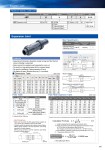
049 Expansion Joint JEP Model ü¢ü¢ü¢ Size ü¢ Rubber E EPDM éuéeéjél ée ViflonRF/FKM-F C ViflonRC/FKM-C JEP Expansion Joint T Connection T Socket U Material U U-PVC J Standard J JIS 020 20 ćo . 100 100 ćo PRODUCT MODEL CODE LIST Expansion Joint āėD1 āėD2 āėD3 āėd1 L Taper 1/T āėd R1 R2 When installing When piping is expanded by heat 2 6 4a 1 7 5 4b 3 āėD1 āėD2 āėD3 āėd1 L Taper 1/T āėd R1 R2 When installing When piping is expanded by heat 2 6 4a 1 7 5 4b 3 Dimensions Diagram āėD1 āėD2 āėD3 āėd1 L Taper 1/T āėd R1 R2 When installing When piping is expanded by heat 2 6 4a 1 7 5 4b 3 üE Expansion/contraction absorption margin is large and the thermal stress of piping is absorbed. üEEasy removal from piping by just loosening the union nut. üENo need for a large piping space with the compact design. üENo need for installation of piping expansion U bend. üENo slipping of pipes. (Because stop ring ćD is provided) Features Size d d1 R1 1/T D2 D1 D3 L R2 mm inch Max. Min. Expansion/ Contraction Margin 20 3/4 20 26.13 24 1/34 35 60 35 243 163 80 25 1 25 32.16 27 1/34 43 70 39 250 170 80 30 11/4 31 38.19 30 1/34 50 82 47 258 178 80 40 11/2 40 48.21 37 1/37 59 100 59 272 192 80 50 2 51 60.25 42 1/37 72 106 72 285 205 80 65 21/2 65 76.60 61 1/48 88 133 88 314 234 80 75 3 78 89.60 64 1/49 105 152 105 330 250 80 100 4 100 114.70 84 1/56 132 210 132 422 322 100 üĪ Dimensions Table (Unit: mm) No. Description pcs. Material ć@ Body 1 U-PVC ćA End Connector (A) 1 U-PVC ćB End Connector (B) 1 U-PVC ü³4a Union Nut (A) . U-PVC ü³4b Union Nut (B)1) 1 U-PVC ćD Stop Ring 1 U-PVC ćE O-Ring (A) 1 EPDM, FKM, ViflonRF (FKM-F), ViflonRC (FKM-C) ćF O-Ring (B) 2 EPDM, FKM, ViflonRF (FKM-F), ViflonRC (FKM-C) 1) Use for 65 to 100 mm. Parts Table ü@ü@ü@ Piping Length L Temperature Difference 5m 10m 20m 30m 40m 50m 60m 70m 80m 10ó¬C 4 7 14 21 28 35 42 49 56 20ó¬C 7 14 28 42 56 70 84 98 112 30ó¬C 11 21 42 63 84 105 126 147 168 40ó¬C 14 28 56 84 112 140 168 196 224 50ó¬C 18 35 70 105 140 175 210 245 280 60ó¬C 21 42 84 126 168 210 252 294 336 70ó¬C 25 49 98 147 196 245 294 343 392 80ó¬C 28 56 112 168 224 280 336 392 448 Pipe Heat Expansion Table (Unit: mm) Material Working Temperature Maximum Working Pressure (Normal Temperature) MPa{kgf/cm2} Connection Socket End Unplasticized Polyvinyl Chloride Pipe (U-PVC) 5-60ó¬C 1.0{10.2} üø Main Specification When installing When piping is expanded by heat üł One piece per 50 m. ü@L: Length of piping that the expansion joint absorbs (mm) üóR: Piping expansion/contraction length Expansion/contraction margin for 75 mm from the dimensions table R2üü80 mm Give margins on both ends 5 mmü~2üü10 mm üóR:üü(80.10) mm ü@ā┐: Heat expansion coefficient of hard polyvinyl chloride pipe 7ü~10.5 (/üÄ) üóéö : Temperature difference 20 (üÄ)