av-en-valves 196 / 246
10秒後にBOOKのページに移動します
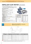
● FLANGED 195 AUTOMATIC FLOW METER / IMPELLER FLOW METER ASIP80 SERIES, IMPELLER FLOW METER ASSPX SERIES IMPELLER FLOW METER ASIP80 SERIES . INSERTION TYPE USING SPECIAL FITTING. . ALL THE WETTED PARTS ARE MADE OF CHEMICAL-RESISTANT PLASTIC (SO THAT THE METER CAN BE USED FOR SEA WATER LINES AND VARIOUS CHEMICAL SOLUTION LINES). TABLE 1 MAX. OPERATING FLUID PRESSURE AND TEMPERATURE FOR SPECIAL FITTING TEMP. (°C) PRESSURE (MPa) U-PVC HI-PVC C-PVC 15mm . 150mm 15mm . 50mm 65mm . 150mm 20 1 1 1 30 0.9 1 0.8 40 0.7 1 0.8 50 0.3 0.6 0.6 60 . 0.6 0.6 70 . 0.4 0.4 80 . 0.2 0.2 90 . 0.2 0.2 TABLE 2 MEASURING RANGE AND K-FACTOR SIZE (mm) FLOW RATE (m3/h) K-FACTOR Min . Max (cc/pulse) 15 0.14 . 6.51 7.1 20 0.23 . 10.18 10.9 25 0.35 . 15.89 16.1 32 0.54 . 24.44 26.8 40 0.90 . 40.69 47.2 50 1.47 . 66.16 66.2 65 2.54 . 114.17 102.2 80 3.35 . 150.80 139.7 100 5.65 . 254.34 213.0 125 8.83 . 397.40 355.4 150 12.05 . 542.15 465.0 NOTES (1) The value of K-factor is only a reference value. (2) Obtain the maximum frequency for each size by calculation. Max. frequency = Max. flow rate / K-factor (Hz) (cc/s) (cc/pulse) (1) Piping condition) It is recommended to secure a fitting installation section of 10D on the upper flow side and 5D in the downstream. (D = Inside pipe diameter) Wiring condition) For wire extension, it is recommended to use shielded wires. (2) For display of flow rate, an indicator is required separately. (3) The appearance and shape of assembled parts may slightly differ from the diagram depending on the sizes. (4) Note that the following fittings are not available: Socket, JIS10K flange……HI-PVC/C-PVC (125 mm, 150 mm) JIS 5K flange……HI-PVC (125 mm, 150 mm), C-PVC (80 mm . 150 mm) NOTES VALVE TYPE IMPELLER FLOW METER ASIP80 SERIES SIZE ASIP81(P/Y/K)・・・・・・・・・・・・・・15mm.80mm ASIP82(P/Y/K)・・・・・・・・・・・・・・100mm.150mm CONNECTION METHOD SOCKET, FLANGED MATERIAL SENSOR BODY WORKING TEMPERATURE HI-PVC・・・・・・・・・・・50°C PP・・・・・・・・・・・・・・・・・・・60°C PVDF・・・・・・・・・・・・・・90°C WORKING PRESSURE 1.0MPa IMPELLER PVDF SHAFT ZIRCONIUM, SILICON-CARBIDE BEARING RUBY O-RING FKM(EPDM) SPECIAL FITTING U-PVC, HI-PVC, C-PVC (See TABLE 1 .) MEASUREMENT FLUID FLUID (EXCEPT HIGH VISCOSITY FLUID AND SLURRY) MAXIMUM WORKING TEMPERATURE 0.90°C FLOW RATE 0.2 - 9 m/s (See TABLE 2 .) RANGEABILITY 1:45 MEASUREMENT ACCURACY ±1.5%(FS) POWER SOURCE DC6 . 24V (Consumption current: 8 mA) OUTPUT SIGNAL 3-WIRE, CURRENT SINKING PULSE (NPN) (20 mA Max.) CABLE 3-CON (3.6 m length) FITTING INSTALLATION Upper flow: 10D Min. Downstream: 5D Min. (D: Inside pipe diameter) BASIC SPECIFICATIONS AUTOMATIC SOCKET FLANGED ■ JIS (Unit: mm) mm U-PVC/HI-PVC U-PVC/HI-PVC L H JIS 10K JIS 5K L H D L H D D d t n e D d t n e 15 164 119 57 150 119 56 500 119 95 70 14 4 15 80 60 9 4 12 20 164 121 57 150 121 56 500 121 100 75 15 4 15 85 65 10 4 12 25 164 121 57 150 121 56 500 121 125 90 15 4 19 95 75 10 4 12 32 164 122 57 150 122 56 500 122 135 100 16 4 19 115 90 12 4 15 40 164 125 57 150 125 56 500 125 140 105 16 4 19 120 95 12 4 15 50 180 128 70 164 128 69 500 128 155 120 20 4 19 130 105 14 4 15 65 190 133 87 190 133 87 500 133 175 140 22 4 19 155 130 14 4 15 80 200 136 102 200 136 102 500 136 185 150 22 8 19 180 145 14 4 19 100 250 168 130 250 168 130 700 168 210 175 22 8 19 200 165 16 8 19 125 322 176 157 - - - 700 176 250 210 24 8 23 235 200 16 8 19 150 390 182 186 - - - 700 182 280 240 26 8 23 265 230 18 8 19 IMPELLER FLOW METER ASIP80 SERIES CONNECTION / FLANGED, SOCKET――JIS